Участник:ASDFS/Оптическая накачка лазера
Материал из Википедии — свободной энциклопедии
 | Это временная версия статьи Оптическая накачка лазера. |

Оптическая накачка лазера подразумевает наличие источника света, оптической системы для концентрации этого света на рабочем теле лазера и собственно рабочего тела лазера. Тип лампы и рабочее тело лазера должны подходить друг другу по спектрам излучения и поглощения соответственно. В качестве источника света обычно применяют:
- электролампы с высоким КПД (газоразрядные, дуговые);
- полупроводниковые источники света (светодиоды или лазеры);
- солнечный свет;
Оптическая накачка лазера, как правило, производится с боковой стороны рабочей среды лазера. Лазеры чаще всего твердотельные (представлены в виде стержня из кристалла или активированного примесями стекла) или лазеры на красителях (в виде стеклянной трубки жидкого раствора красителя или струи с «поперечной прокачкой» раствора красителя). Для наиболее эффективного использования энергии излучения, лампа и активная среда находятся в зеркальной полости, которая направляет большую часть света лампы на рабочую среду.
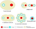
В наиболее распространенной конфигурации усиливающая среда в форме стержня расположена на одной из геометрических центров зеркальной полости, у которого поперечное, перпендикулярное к оси стержня сечение имеет форму эллипса. Трубка лампы-вспышки установлена в другом фокусе эллипса. Часто покрытие зеркала выбрано с учетом длины волн, которые короче длины волны генерации лазера или поглощения активной примеси, чтобы свести к минимуму образование тепловой линзы в стержне. В других случаях для более длинных волн используется поглотитель — на лампу надевают цилиндрическую рубашку, так называемую облегающую трубку. Эта облегающая трубка обычно представляет собой стекло, которое поглощает на непригодных длинах волн, например ультрафиолета, или поток охлаждающей воды, которая поглощает инфракрасное излучение. Часто защитной оболочкой служит диэлектрическое покрытие, которое отражает свет с непригодными длинами волн обратно в лампу. Этот свет поглощается и частично переизлучается в соответствующие длины волн. Облегающая трубка служит также механической защитой в случае порчи лампы.
Малые эллипсы создают малое количество отражений (так называемое состояние «сильной связи»), что обеспечивает более высокую интенсивность освещения в центре стержня[1] Для одноламповой головки, если лампа и стержень одного диаметра, облегающий эллипс (который в два раза шире диаметра), как правило, наиболее эффективен для освещения стержня. В общем можно увеличить длину стержня и лампы, чтобы минимизировать эффекты потерь на торцах и обеспечить достаточное усиление по длине среды. Длинные лампы также более эффективны при преобразовании электрической энергии в свет за счет более высокого электрического сопротивления[2]Но если стержень слишком длинный, то состояние в «режиме суперлюминесценции» может истощить энергию стержня прежде, чем она сможет достаточно накачиваться.[3] Чтобы минимизировать эти потери. на торцы стержня часто наносится просветляющая пленка или их срезают под углом Брюстера.[4] Зеркальное покрытие прямо на торцах стержня или установка зеркал прямо на головке лазера также эффективно уменьшают потери.[5]
Variations on this design use more complex mirrors composed of overlapping elliptical shapes, to allow multiple flashlamps to pump a single rod. This allows greater power, but are less efficient because not all of the light is correctly imaged into the rod, leading to increased thermal losses. These losses can be minimized by using a close-coupled cavity. This approach may allow more symmetric pumping, increasing beam quality, however.[5]
Another configuration uses a rod and a flashlamp in a cavity made of a diffuse reflecting material, such as spectralon or powdered barium sulfate. These cavities are often circular or oblong, as focusing the light is not a primary objective. This doesn’t couple the light as well into the lasing medium, since the light makes many reflections before reaching the rod, but often requires less maintenance than metalized reflectors.[6] The increased number of reflections is compensated for by the diffuse medium’s higher reflectivity: 99 % compared to 97 % for a gold mirror.[7] This approach is more compatible with unpolished rods or multiple lamps.
Parasitic modes occur when reflections are generated in directions other than along the length of the rod, which can use up energy that would otherwise be available to the beam. This can be a particular problem if the barrel of the rod is polished. Cylindrical laser rods support whispering gallery modes due to total internal reflection between the rod and the cooling water, which reflect continuously around the circumference of the rod. Light pipe modes can reflect down the length of the rod in a zig-zag path. If the rod has an antireflection coating, or is immersed in a fluid that matches its refractive index, it can dramatically reduce these parasitic reflections. Likewise, if the barrel of the rod is rough ground (frosted), or grooved, internal reflections can be dispersed.[8]
Pumping with a single lamp tends to focus most of the energy on one side, worsening the beam profile. It is common for rods to have a frosted barrel, to diffuse the light, providing a more even distribution of light throughout the rod. This allows more energy absorption throughout the gain medium for a better transverse mode. A frosted flow tube or diffuse reflector, while leading to lowered transfer efficiency, helps increase this effect, improving the gain.[9]
Laser host materials are chosen to have a low absorption; only the dopant absorbs. Therefore any light at frequencies not absorbed by the doping will go back into the lamp and reheat the plasma, shortening lamp life.
Накачка лампой-вспышкой
[править | править код]Flashlamps were the earliest energy source for lasers. They are used for high pulsed energies in both solid-state and dye lasers. They produce a broad spectrum of light, causing most of the energy to be wasted as heat in the gain medium. Flashlamps also tend to have a short lifetime.[10] The first laser consisted of a helical flashlamp surrounding a ruby rod.
Quartz flashlamps are the most common type used in lasers, and, at low energies or high repetition rates, can operate at temperatures as high as 900 °C. Higher average powers or repetition rates require water cooling. The water usually has to wash across not only the arc length of the lamp, but across the electrode portion of the glass as well. Water-cooled flashlamps are usually manufactured with the glass shrunken around the electrode to allow direct cooling of the tungsten. If the electrode is allowed to heat much more than the glass thermal expansion can crack the seal.[11]
Lamp lifetime depends primarily on the energy regime used for the particular lamp. Low energies give rise to sputter, which can remove material from the cathode and redeposit it on the glass, creating a darkened, mirrored appearance. The life expectancy at low energies can be quite unpredictable. High energies cause wall ablation, which not only gives the glass a cloudy appearance, but also weakens it structurally and releases oxygen, affecting pressure, but at these energy levels the life expectancy can be calculated with a fair amount of accuracy.[11]
Pulse duration can also affect lifetime. Very long pulses can strip large amounts of material from the cathode, depositing it on the walls. With very short pulse durations, care must be taken to ensure that the arc is centered in the lamp, far away from the glass, preventing serious wall ablation.[11] External triggering is not usually recommended for short pulses.[11] Simmer voltage triggering is usually used for extremely fast discharges, as are used in dye lasers, and often combine this with a «pre-pulse technique», where as a small flash is initiated just milliseconds before the main flash, to preheat the gas for a faster rise time.[12]
Dye lasers sometimes use "axial pumping, " which consists of a hollow, annular shaped flashlamp, with the outer envelope mirrored to reflect suitable light back to the center. The dye cell is placed in the middle, providing a more even distribution of pumping light, and more efficient transfer of energy. The hollow flashlamp also has lower inductance than a normal flashlamp, which provides a shorter flash discharge. Rarely, a «coaxial» design is used for dye lasers, which consists of a normal flashlamp surrounded by an annular shaped dye cell. This provides better transfer efficiency, eliminating the need for a reflector, but diffraction losses cause a lower gain.[13]
The output spectrum of a flashlamp is primarily a product of its current density.[11] After determining the «explosion energy» for the pulse duration, (the amount of energy that will destroy it in one to ten flashes), and choosing a safe energy level for operation, the balance of voltage and capacitance can be adjusted to center the output anywhere from the near infrared to the far ultraviolet. Low current densities result from the use of very high voltage and low current.[11][14] This produces broadened spectral lines with the output centered in the near-IR, and is best for pumping infrared lasers such as Nd:YAG and erbium:YAG. Higher current densities broaden the spectral lines to the point where they begin to blend together, and continuum emission is produced. Longer wavelengths reach saturation levels at lower current densities than shorter wavelengths, so as current is increased the output center will shift toward the visual spectrum, which is better for pumping visible light lasers, such as ruby.[2] At this point, the gas becomes nearly an ideal «greybody radiator.»[14] Even higher current densities will produce blackbody radiation, centering the output in the ultraviolet.
Xenon is used extensively because of its good efficiency,[11] although krypton is often used for pumping neodymium doped laser rods. This is because the spectral lines in the near-IR range better match the absorption lines of neodymium, giving krypton better transfer efficiency even though its overall power output is lower.[11][15][16] This is especially effective with Nd:YAG, which has a narrow absorption profile. Pumped with krypton, these lasers can achieve up to twice the output power obtainable from xenon.[17] Spectral line emission is usually chosen when pumping Nd:YAG with krypton, but since all of xenon’s spectral lines miss the absorption bands of Nd:YAG, when pumping with xenon the continuum emission is used.[18]
-
 Различные конструкции отражателей лазерной головки.
 -
 Лампы для накачки лазера: верхние три ксеноновые, а нижняя - криптоновая
 -
 Для очень быстрого разряда ипользуется внешний запуск. Из-за очень высокой скорости (3.5 мкс), ток не только не полностью заполняет трубку и возбуждает ксенон, но и все ещё находится в непосредственном контакте со стеклом.
 -
 При соответствующей плотности тока, спектры излучения ламп-вспышек с различными газами близки к спектру излучения серого тела.
 -
![Оптическая накачка лазерного стержня (внизу) дуговой лампой (сверху). Красный: горячий. Синий: холодный. Зелёный: свет. Не зелёные стрелки: поток воды. Синий: металл. Светлые цвета: плавленый кварц.[19][20][21]](https://upload.wikimedia.org/wikipedia/commons/thumb/7/7b/Long_arc_lamp.svg/120px-Long_arc_lamp.svg.png) Оптическая накачка лазерного стержня (внизу) дуговой лампой (сверху). Красный: горячий. Синий: холодный. Зелёный: свет. Не зелёные стрелки: поток воды. Синий: металл. Светлые цвета: плавленый кварц.[19][20][21]
Оптическая накачка лазерного стержня (внизу) дуговой лампой (сверху). Красный: горячий. Синий: холодный. Зелёный: свет. Не зелёные стрелки: поток воды. Синий: металл. Светлые цвета: плавленый кварц.[19][20][21] -
 Спектры излучения газоразрядных ламп заполненые различными инертными газами.


![Оптическая накачка лазерного стержня (внизу) дуговой лампой (сверху). Красный: горячий. Синий: холодный. Зелёный: свет. Не зелёные стрелки: поток воды. Синий: металл. Светлые цвета: плавленый кварц.[19][20][21]](/ru/%D0%A4%D0%B0%D0%B9%D0%BB:Long_arc_lamp.svg)

Дуговая лампа
[править | править код]Arc lamps are used for pumping rods that can support continuous operation, and can be made any size and power. Typical arc lamps operate at a voltage high enough to maintain the certain current level for which the lamp was designed to operate. This is often in the range of 10 to 50 amps. Due to their very high pressures, arc lamps require specially designed circuitry for start up, or «striking» the arc. Striking usually occurs in three phases. In the triggering phase, an extremely high voltage pulse from the «series triggering» transformer creates a spark streamer between the electrodes, but the impedance is too high for the main voltage to take over. A «boost voltage» phase is then initiated, where a voltage that is higher than the voltage drop between the electrodes is driven through the lamp, until the gas is heated to a plasma state. When impedance becomes low enough, the «current control» phase takes over, where as the main voltage begins to drive the current to a stable level.[11]
Arc lamp pumping takes place in a cavity similar to a flashlamp pumped laser, with a rod and one or more lamps in a reflector cavity. The exact shape of the cavity is often dependant on how many lamps are used. The main difference is in the cooling. Arc lamps need to be cooled with water, ensuring that the water washes beyond the glass, and across the electrode connectors as well. This requires the use of deionized water with a resistivity of at least 200 kilohms, to keep from shorting out the circuit and corroding the electrodes through electrolysis. Water is typically channeled through a flow tube at a rate of 4 to 10 liters per minute.[11]
Arc lamps come in nearly all of the noble gas types, including xenon, krypton, argon, neon, and helium, which all emit spectral lines that are very specific to the gas. The output spectrum of an arc lamp is mostly dependant on the gas type, being narrow band spectral lines very similar to a flashlamp operated at low current densities. The output is highest in the near infrared, and are usually used to pump infrared lasers such as Nd:YAG.
Лазерная накачка
[править | править код]A laser of a suitable type can be used to pump another laser. The pump laser’s narrow spectrum gives it much more efficient energy transfer than flashlamps. Diode lasers pump solid state lasers and liquid dye lasers. A ring laser design is often used, especially in dye lasers. The ring laser uses three or more mirrors to reflect light in a circular path. This helps eliminate the standing wave generated by most Fabry–Pérot resonators, leading to a better use of the gain medium’s energy.[22]
Солнечная накачка
[править | править код]A solar-pumped laser uses solar radiation as a pump source.[23][24]
Примечания
[править | править код]- ↑ Solid-state laser engineering by Walter Koechner — Springer-Verlag 1965 Page 376
- ↑ 1 2 Oliver, J. R. (1969). "A Comparison of Rare-Gas Flashlamps". I.E.E.E. Journal of Quantum Electronics. 5 (5): 232—7. Bibcode:1969IJQE....5..232O. doi:10.1109/JQE.1969.1075765. ISSN 0018-9197.
((cite journal)): Неизвестный параметр|coauthors=игнорируется (|author=предлагается) (справка); Неизвестный параметр|month=игнорируется (справка) - ↑ Solid-state laser engineering by Walter Koechner — Springer-Verlag 1965 Page 192
- ↑ Solid-state laser engineering by Walter Koechner — Springer-Verlag 1965 Page 194
- ↑ 1 2 Solid-state laser engineering by Walter Koechner — Springer-Verlag 1965 Page 368—376
- ↑ Solid-state laser engineering by Walter Koechner — Springer-Verlag 1965 Page 368—373
- ↑ Economy front surface mirrors. Thorlabs.com. Дата обращения: 1 марта 2009.
- ↑ Solid-state laser engineering by Walter Koechner — Springer-Verlag 1965 Page 193—194
- ↑ Solid-state laser engineering by Walter Koechner — Springer-Verlag 1965 Page 380—381
- ↑ Edgerton, Harold E. Electronic Flash Strobe. — MIT Press. — ISBN 0-262-55008-3.
- ↑ 1 2 3 4 5 6 7 8 9 10 High Performance Flash and Arc Lamps (pdf). PerkinElmer. Дата обращения: 3 февраля 2009.
- ↑ Holzrichter, J. F. (1969). "Design and analysis of flashlamp systems for pumping organic dye lasers". Annals of the New York Academy of Sciences. 168 (3): 703—14. Bibcode:1969NYASA.168..703H. doi:10.1111/j.1749-6632.1969.tb43155.x. PMID 5273396.
((cite journal)): Неизвестный параметр|coauthors=игнорируется (|author=предлагается) (справка); Неизвестный параметр|month=игнорируется (справка) - ↑ «Principles of Lasers», by Orazio Svelto
- ↑ 1 2 Klipstein, Don General Xenon Flash and Strobe Design Guidelines. Дата обращения: 3 февраля 2009.
- ↑ Dishington, R. H. (1974). "Flashlamp discharge and laser efficiency". Applied Optics. 13 (10): 2300—2312. Bibcode:1974ApOpt..13.2300D. doi:10.1364/AO.13.002300. PMID 20134680.
((cite journal)): Неизвестный параметр|coauthors=игнорируется (|author=предлагается) (справка) - ↑ Lamp-pumped Lasers. Encyclopedia of Laser Physics and Technology. RP Photonics. Дата обращения: 3 февраля 2009.
- ↑ Solid-state laser engineering by Walter Koechner — Springer-Verlag 1965 Page 335
- ↑ Solid-state lasers: a graduate text By Walter Koechner, Michael Bass — Springer-Verlag 2003 Page 190
- ↑ Lamp4462 (gif). Sintec Optronics. Дата обращения: 1 марта 2009.
- ↑ Laser Lamps. New Source Technology. Дата обращения: 1 марта 2009.
- ↑ Lamp5028 (gif). Sintec Optronics. Дата обращения: 1 марта 2009.
- ↑ Laser fundamentals by William Thomas Silfvast — Cambridge University Press 1996 Page 397—399
- ↑ De Young, R. J.; Weaver, W. R. (18 August 1986). "Low-threshold solar-pumped laser using C2F5I". Applied Physics Letters. 49 (7): 369—370. Bibcode:1986ApPhL..49..369D. doi:10.1063/1.97589.
- ↑ Appl. Phys. Lett. 90: 261120. 25 June 2007.
((cite journal)):|title=пропущен или пуст (справка)
Text is available under the CC BY-SA 4.0 license; additional terms may apply.
Images, videos and audio are available under their respective licenses.
